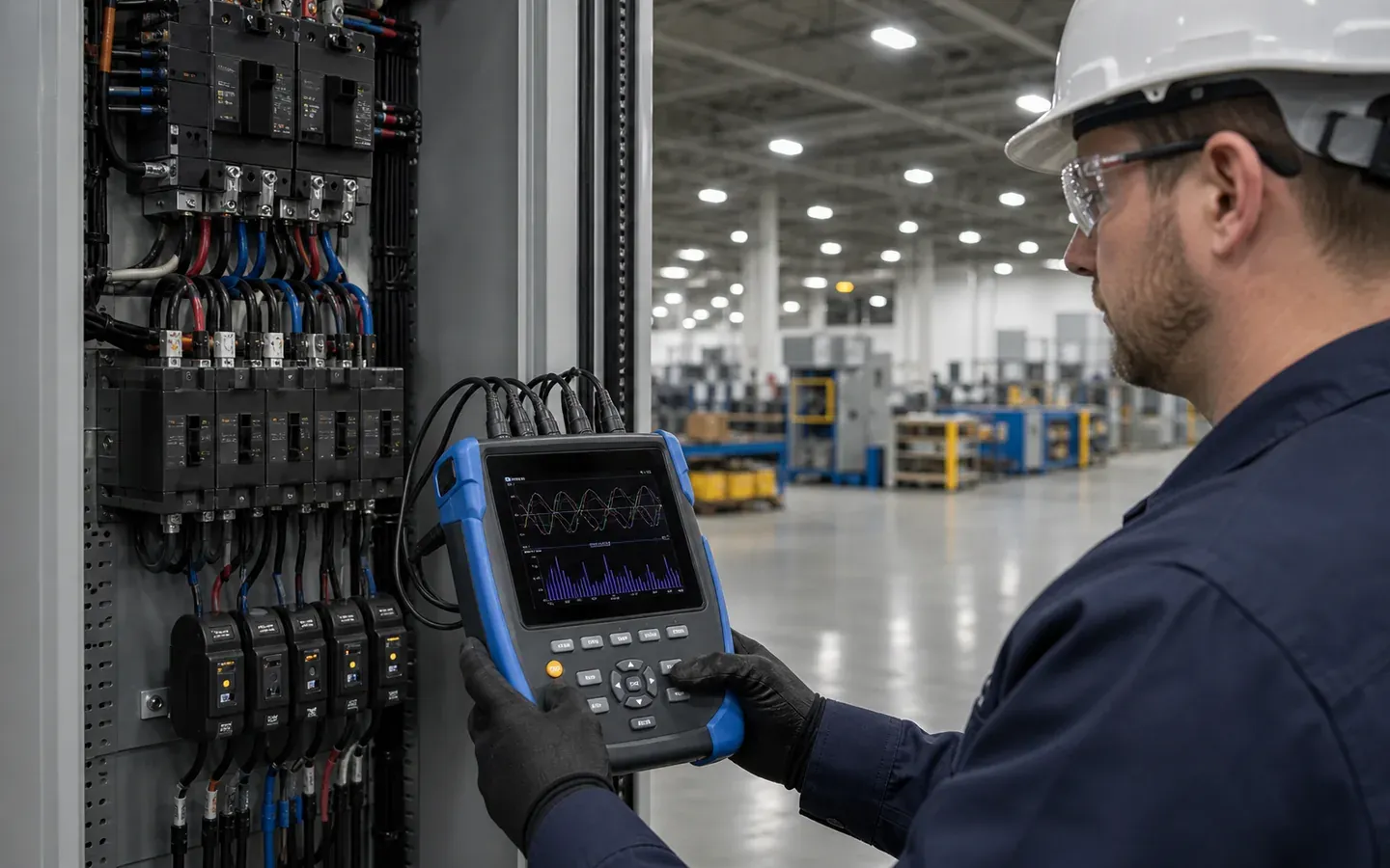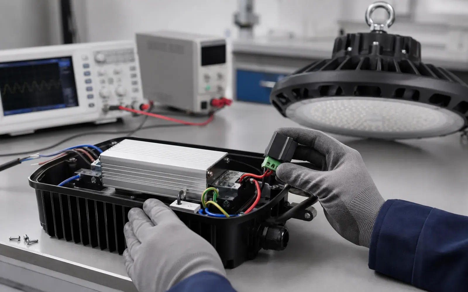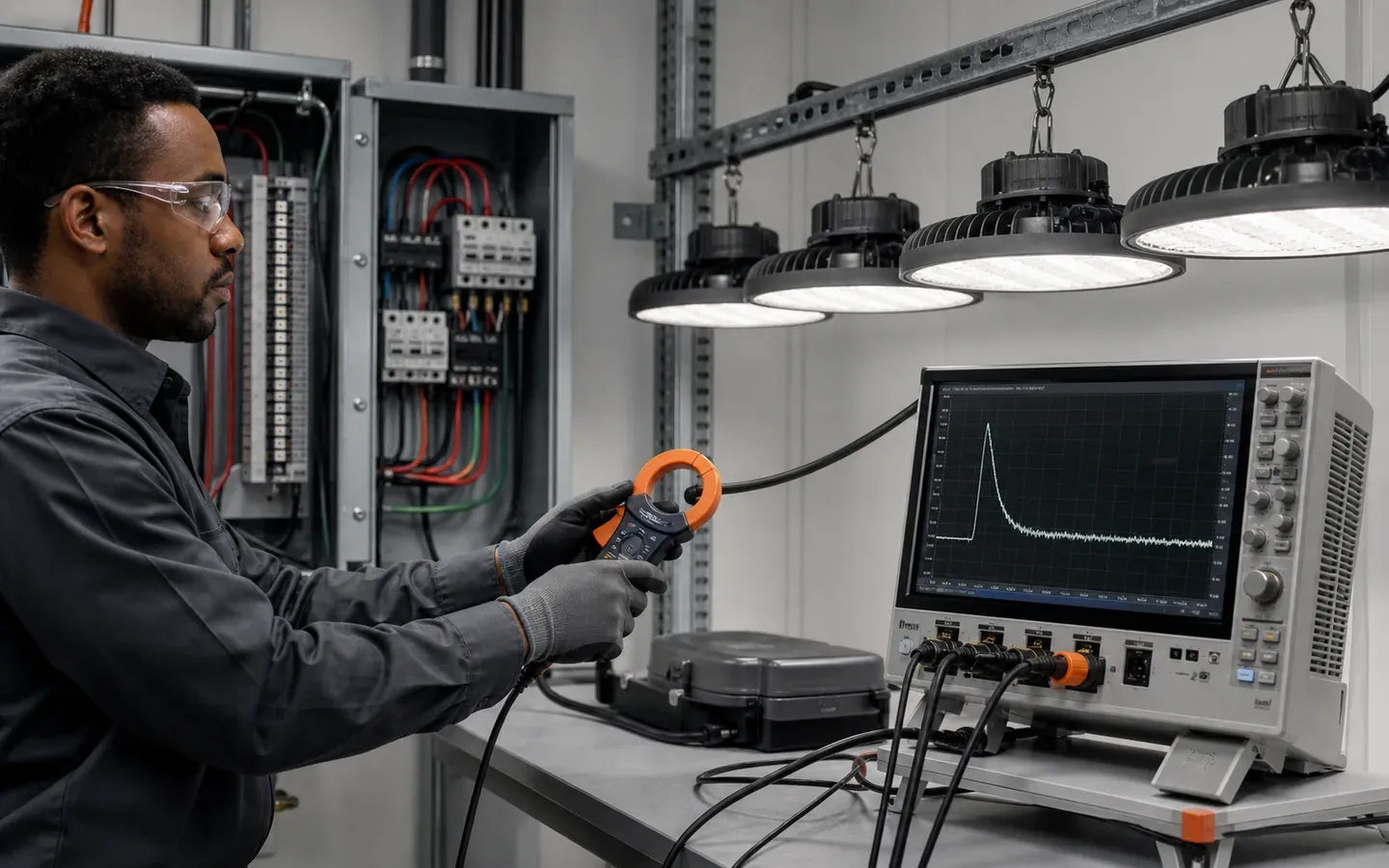
A lighting circuit can be well below its steady-state ampere rating and still trip when dozens of LED drivers start together. The input capacitors charge during a short pulse, so breaker and contactor selection must consider inrush amplitude, pulse duration and the number of luminaires energized at once.
Buyer takeaway: ask for the manufacturer’s maximum luminaire quantity per breaker type at the project voltage. Watts divided by volts is not enough for startup coordination.
Distinguish inrush from a surge event
Inrush current is a normal startup characteristic of the driver. A lightning or switching surge is an external transient disturbance. They require different evidence and mitigation.
For surge exposure and SPDs, use the LED high-bay surge guide. For inrush, focus on driver input capacitance, switching point, line impedance and protective-device curves.
Request both peak and pulse width
An isolated peak-current value is difficult to apply without duration and test conditions. Request:
- input voltage and frequency;
- cold-start or warm-restart condition;
- peak current, usually shown as Ipeak;
- pulse width and its measurement definition;
- source impedance used in testing;
- maximum drivers per stated breaker curve/rating;
- effect of control gear, relays and emergency modules.
Signify’s industrial-driver guidance describes inrush as the brief current charging input capacitors and recommends using driver-specific Ipeak and duration data with breaker-manufacturer guidance (Xitanium design-in guide).
Do not multiply peaks arithmetically
Adding every Ipeak assumes perfectly simultaneous identical pulses and ignores wiring impedance, switching angle and component tolerances. On the other hand, ignoring accumulation can cause nuisance trips. Use tested manufacturer tables or a calculation accepted by the electrical designer and protective-device supplier.
| Input needed | Why it matters |
|---|---|
| Breaker brand/type/rating | Magnetic trip curves differ |
| Supply voltage | Driver current and table limits change |
| Luminaire count | Inrush accumulates by switched group |
| Switching method | Relay timing and zero-cross behavior matter |
| Cable length/impedance | Influences pulse magnitude |
| Restart scenario | Hot re-strike may differ from cold start |
Check contactors and control relays
The breaker is not the only device exposed. Relay contacts and contactors need a rating suitable for capacitive LED loads. A device with adequate steady current can weld or wear prematurely under repetitive high peaks.
Confirm maximum load per control channel, expected switching cycles and whether zero-cross switching is used. Sensors that switch whole aisles directly may need an interposing contactor or another architecture.
Use staged startup where appropriate
Large warehouses can energize zones sequentially after power restoration. A short delay between groups reduces simultaneous inrush and can make generator or transfer operation more stable. The sequence must preserve required emergency and safe-route lighting.
Document how the system behaves after an outage, a controls reboot and a manual override. Test these scenarios during commissioning rather than only switching individual fixtures.
Coordinate steady-state design separately
After the inrush check, verify cable ampacity, voltage drop, protective-device rating, leakage current and operating current under the applicable electrical code. Power factor and harmonic current influence the system but are not substitutes for inrush data; see the high-bay PF and THD guide.
When comparing UFO high bays and linear high bays, use the offered driver configuration. Two luminaires with equal wattage can have different startup limits.
RFQ clause
“Submit driver and complete-luminaire inrush data at the scheduled voltage, including Ipeak, pulse width, measurement conditions and maximum quantity per proposed breaker type/rating. State control-relay or contactor limits and hot-restart behavior. Supplier shall notify the buyer before changing the driver or input-stage design.”
The electrical engineer must make the final protective-device selection using local codes, fault levels and the complete distribution design.