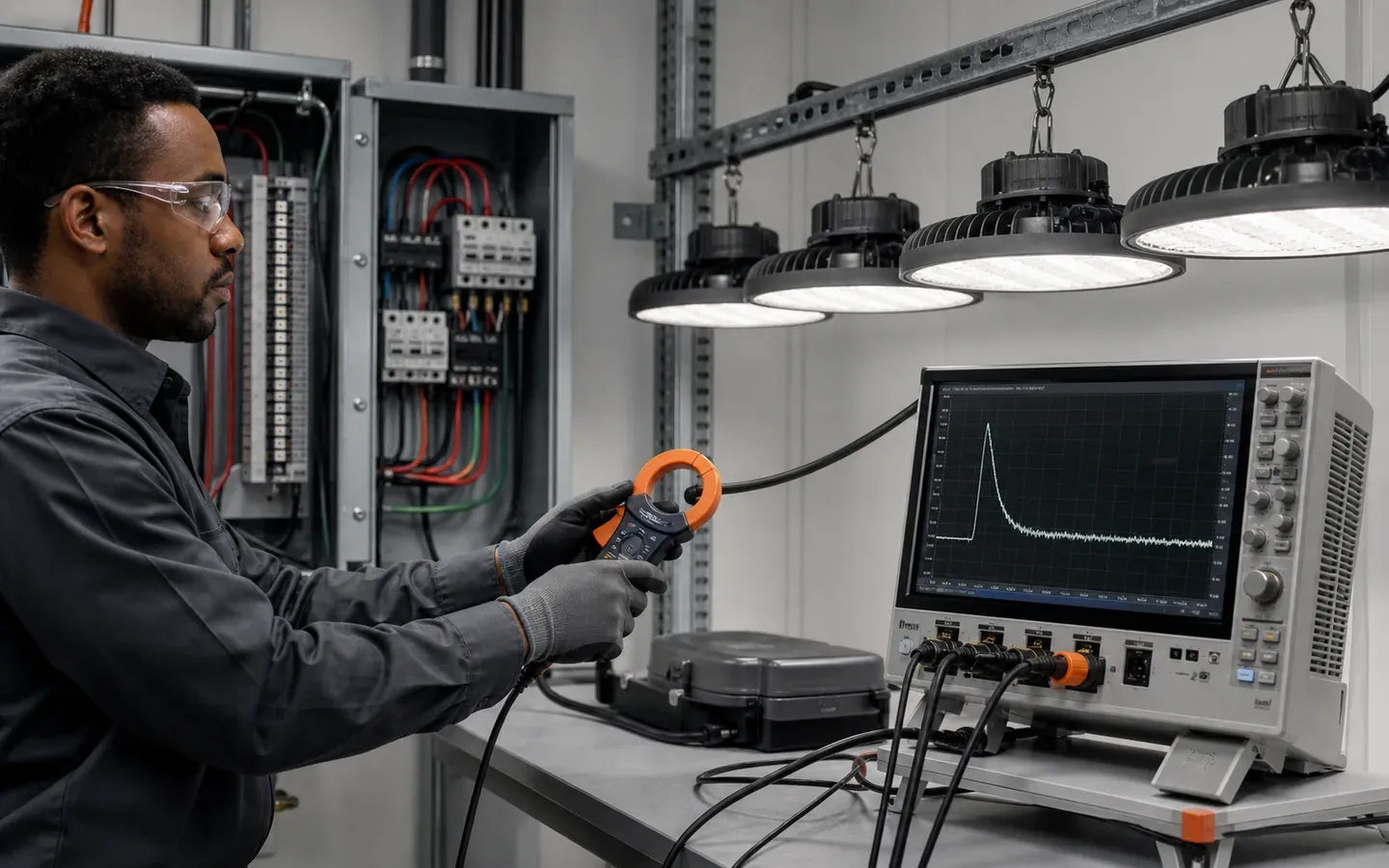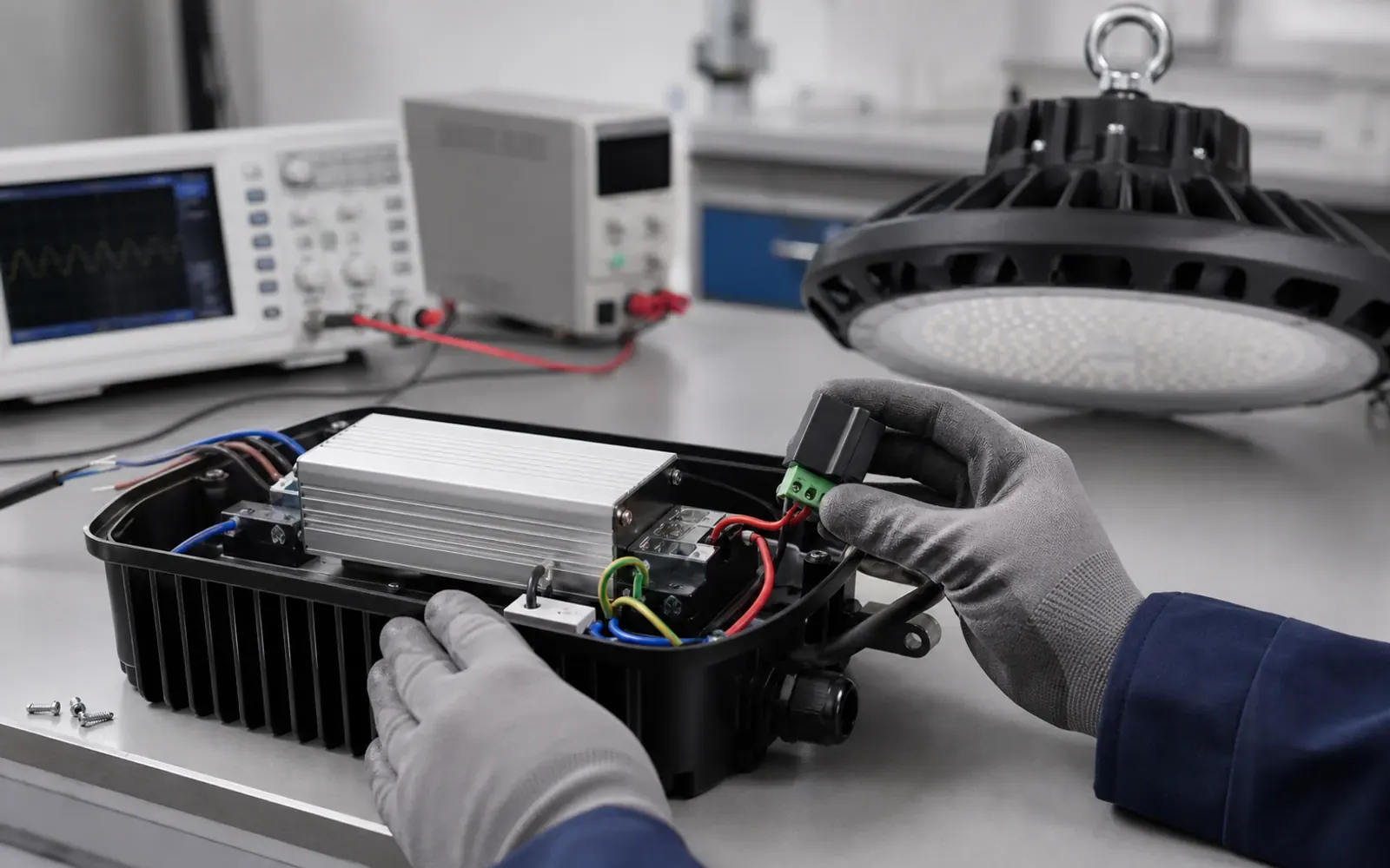
High efficacy does not describe how an LED high bay interacts with the electrical system. On a large factory project, buyers should review real power, apparent power, power factor, harmonic current and behavior across voltage and dimming states.
Buyer takeaway: specify the measurement condition and require model-specific reports. A single “PF greater than 0.95” line at full load does not predict performance at minimum dimming or across every voltage option.
Separate the terms
Power factor is the ratio of real power to apparent power. It can be affected by phase displacement and waveform distortion. THDi describes current-waveform harmonic distortion relative to the fundamental under the stated method. The two values are related but not interchangeable.
IEC 61000-3-2 addresses harmonic-current limits for electrical and electronic equipment up to 16 A per phase connected to public low-voltage systems and includes lighting-equipment conditions (IEC 61000-3-2 overview). Determine the applicable standard and class with the compliance professional; do not create a project limit by copying a consumer lamp datasheet.
Define operating points
Request data at the project’s nominal voltage and frequency, plus relevant extremes. For controllable high bays, ask for full output and representative dimmed points. Some drivers maintain good full-load performance but draw a more distorted current at low output.
Record:
- input watts, volts and current;
- PF and displacement factor if available;
- THDi and harmonic spectrum where required;
- driver output current or dimming level;
- control state and connected accessories;
- ambient and stabilization condition;
- test standard and instrument method.
Review the complete ordered luminaire
Driver data is useful, but emergency modules, sensors and auxiliary supplies can change standby or low-load behavior. Verify the full offered configuration and ensure the test report identifies the driver model and programming.
For field-adjustable wattage, request each intended setting or a justified worst case. Lock the approved setting at commissioning and record it on the asset schedule.
| Procurement risk | Practical check |
|---|---|
| Generic PF claim | Match report to exact model and voltage |
| THDi only at full load | Review scheduled dimming points |
| Driver substitution | Put driver code on controlled BOM |
| Phase imbalance | Distribute final circuit loads by phase |
| Neutral heating concern | Ask engineer to review harmonic spectrum |
| Generator operation | Test restoration and low-load stability |
Model the installation, not just one fixture
Aggregate many electronic loads across a three-phase system. The electrical engineer should review phase balance, neutral loading, transformer and generator compatibility, voltage distortion and interaction with other plant loads.
Do not assume that high individual THDi values add directly or cancel reliably; system results depend on harmonic magnitude and phase angle across loads. Measure at representative panels during the pilot or commissioning stage when power quality is a project risk.
Keep inrush as a separate calculation
PF and THDi describe steady periodic behavior, while startup inrush is a short event. A circuit can pass the harmonic review and still nuisance-trip at switch-on. Use the inrush-current and breaker-sizing guide for startup coordination and the surge-protection guide for transient overvoltage.
Include controls and failure states
Test high-end trim, minimum dim level, sensor-off state and power restoration. If the driver supports standby power or networked reporting, include auxiliary consumption in the controls energy model.
For system protocol decisions, see DALI-2 versus 0–10V high-bay controls. Match the control option on the test sample to the one ordered for UFO or linear high bays.
RFQ clause
“Submit model-specific input power, current, power factor and harmonic-current data at the scheduled supply and full output. For dimmable products, include agreed intermediate and minimum operating points. Identify the driver and all auxiliary loads. No driver or programming change is permitted without updated electrical evidence and buyer approval.”
The project electrical engineer remains responsible for code compliance and system-level assessment. The supplier’s report is an input to that design, not a substitute for it.