The solar panel on a street light is both an energy collector and a wind-exposed surface. Pole and foundation selection must account for panel orientation, luminaire area, equipment weight, local wind, terrain, soil and structural code—not only nominal pole height.
Buyer takeaway: do not accept a universal foundation drawing without site inputs and an engineer’s design basis. The same eight-meter solar light can impose very different loads in a sheltered town and a cyclone-prone coast.
Issue a structural site data sheet
Provide the responsible structural engineer with:
- project coordinates and elevation;
- governing structural code and design life;
- basic/design wind speed and averaging convention;
- terrain/exposure category and topographic effects;
- wind direction requirements;
- ice or snow loads where applicable;
- seismic and vehicle-impact requirements;
- soil report, groundwater and corrosion conditions;
- pole setback and any breakaway requirement.
Wind values from different codes are not directly interchangeable. State the code, units, return period and load factors rather than writing only “wind resistant to 150 km/h.”
Calculate the complete projected area
Include the solar module, luminaire, bracket, battery enclosure, sensor and pole. Record projected area and drag assumptions for relevant wind directions. An adjustable panel can create a larger governing area at one orientation.
Ask the equipment supplier for dimensioned drawings, weights, centers of gravity and maximum effective projected area. The structural engineer—not the lighting salesperson—should apply the site loads and combinations.
Review pole strength and fatigue
Check material grade, taper, wall thickness, weld details, galvanizing or coating, access-door reinforcement, base plate, anchor bolts and bracket connection. Wind-induced vibration can accumulate fatigue damage even below an ultimate storm load.
FHWA research notes that lightweight high-mast and luminaire supports can be susceptible to wind-induced vibration and fatigue at welded details (FHWA fatigue overview). Apply the structural standard required in the project jurisdiction.
| Structural item | Required submittal |
|---|---|
| Pole shaft | Material, geometry, thickness and calculation |
| Welds | Detail, process and inspection criteria |
| Base plate/anchors | Dimensions, grades, templates and tightening method |
| Brackets | Load path, bolts and locking method |
| Equipment | Weight, center of gravity and projected area |
| Corrosion system | Surface preparation, coating/galvanizing and repair |
Design the foundation from soil and loads
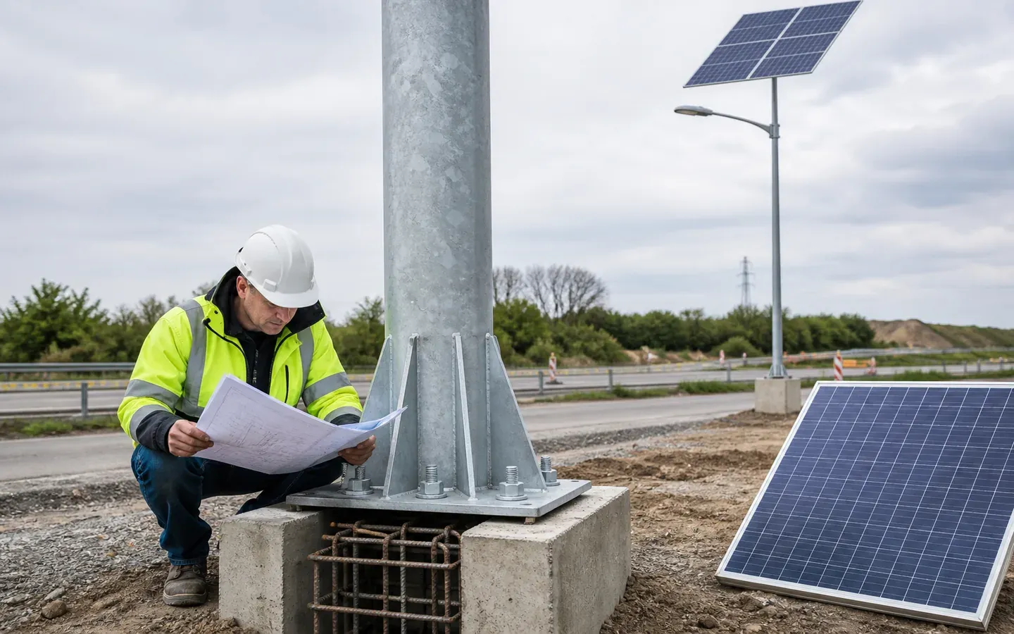
Foundation diameter and depth depend on overturning moment, lateral shear, soil strength, groundwater, frost and constructability. A generic concrete block can fail by rotation, sliding, inadequate anchor development or poor installation even if the pole itself is strong.
Provide geotechnical parameters and have a qualified engineer design the foundation. Define concrete strength, reinforcement, anchor cage, cover, conduit entry, drainage, finished level and curing requirements.
FHWA describes the foundation, base plate, anchor rods, pole and luminaire as connected structural-support components (structural support inspection guide). Treat them as one load path.
Coordinate solar performance with structure
Changing panel tilt or size affects wind loading and energy yield. Do not increase the module area after structural approval without recalculation. Conversely, do not flatten or shade the panel to solve a structural issue without repeating the energy model.
Use the solar street light battery and autonomy guide to size energy components from local solar data and operating profile. Then freeze the panel, battery and luminaire configuration used in both calculations.
Detail cables, water and corrosion
Seal cable entries without creating trapped water. Separate dissimilar metals and specify fasteners for the exposure. In coastal areas, define coating preparation and maintenance rather than relying on a salt-spray-hour claim.
Make battery and controller access safe without weakening the pole or allowing unauthorized entry. The all-in-one solar street light configuration should be reviewed with the selected pole bracket and panel orientation.
Inspect installation and handover
Verify excavation, reinforcement, anchor template, concrete placement, verticality, grout, bolt tightening and drainage before accepting the pole. Photograph hidden work and record concrete batches. After erection, check panel angle, bracket locks and cable strain relief.
Handover should include stamped calculations where required, as-built foundations, material certificates, weld/galvanizing records, torque records and an inspection schedule.
RFQ clause
“Supplier shall submit equipment weights, centers of gravity, maximum projected areas and dimensioned interfaces for the complete solar street light. Pole and foundation shall be designed by the responsible engineer to the stated site wind, terrain, soil and governing code. Generic foundation drawings without a documented design basis are not acceptable.”
This keeps the lighting, solar and civil packages aligned before fabrication begins.