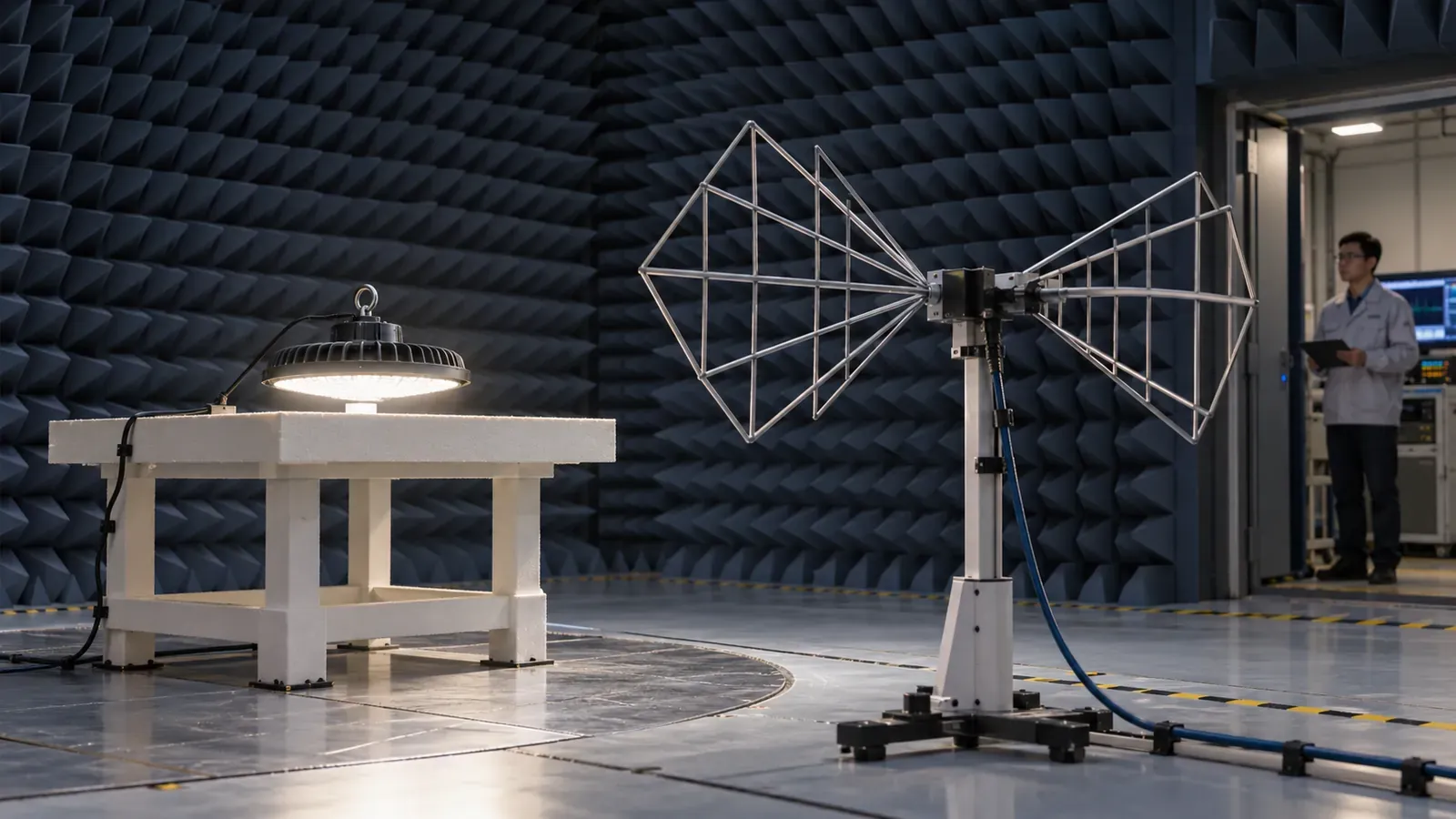
An LED high bay can meet its lumen and wattage targets while its procurement file still leaves an important question unanswered: does the EMC evidence cover the luminaire being shipped? A report for a driver, a different wattage or a sensor-free model can look convincing without establishing coverage for the buyer’s selected assembly.
For importers and industrial-project buyers, an LED high bay EMC test report should link the tested configuration to the quotation, approved sample and production bill of materials. This guide explains how to review that chain before a bulk order, including dimming and sensor variants.
What to request before approving the order
Request complete reports covering applicable emissions and immunity requirements, with the exact standards and editions, product identification, operating modes, cable arrangement, results and observations. Add a model-coverage matrix for variants and a written change-control process. Ask the laboratory or compliance reviewer to confirm the standards appropriate to the destination market and product features.
A report is evidence supporting a compliance assessment. Its relevance depends on its scope, configuration and applicable requirements; a laboratory logo alone does not settle those questions.
1. Separate emissions, immunity and power quality
The standards answer different questions. CISPR 15 addresses radiofrequency disturbances emitted by lighting equipment. IEC 61547:2020 addresses electromagnetic immunity of general lighting equipment. Passing an emissions test does not establish immunity, and the reverse is also true.
| Evidence area | Procurement question | What to inspect |
|---|---|---|
| Conducted and radiated emissions | What disturbance does the assembly produce? | Applicable ports, methods, limits and measured results |
| Immunity | How does the assembly behave when disturbances are applied? | Applied tests, levels, performance criteria and observed response |
| Harmonic current | How does the input current affect supply power quality? | Applicable requirement and offered configuration |
| Voltage fluctuations and flicker | What supply disturbance does the product create? | Applicable scope and measurement conditions |
The IEC CISPR application guide identifies IEC 61547, IEC 61000-3-2 and IEC 61000-3-3 as related requirements in many lighting applications, with applicability qualifications. Use the power-factor and THD guide for that separate evidence area. A low THD number does not replace a radiofrequency emissions report.
Specify the edition and relevant national or regional adoption in the compliance file. Where a quotation cites CISPR 15:2018, clarify whether the required assessment includes Amendment 1:2024; an old report should be reviewed against the actual procurement basis. Do not assume that the international publication alone proves every destination-market requirement.
2. Check whether the driver report covers the complete high bay
The complete assembly includes the LED load, enclosure, bonding or earthing arrangement where applicable, mains lead, internal wiring and control connections. Changes to those elements can change EMC behavior. A driver report is useful component evidence, but it does not automatically establish the result for every luminaire assembled around it.
Ask the supplier to identify:
- the exact high-bay model, wattage, driver model and revision;
- LED-board configuration and driver-current setting;
- housing and electrical protection class;
- cable types, lengths, routing and connected ports;
- dimming interface, sensor and any radio module;
- tested sample photographs and identification labels.
If an engineer extends coverage from one tested variant to others, request the written rationale and its limits. Similar product names or equal rated wattage are insufficient by themselves. The approval should identify which versions are covered, which require further review and who made that decision.
3. Include controls and representative operating modes
Maximum wattage is not automatically the worst case for every emissions test. A dimmable driver may behave differently at low output, and added control wiring introduces another configuration to assess. Let the laboratory select representative or worst-case modes under the relevant method and record the justification.
For a DALI or 0–10 V high bay, list the tested dimming settings, connected controller, control-cable arrangement and sensor state. For an emergency version, state which normal and emergency configurations the assessment covers. Use the DALI-2 versus 0–10 V procurement guide to define the offered interface before checking the report.
CISPR 15 does not replace the applicable assessment of a radio module’s intentional transmissions. A wireless sensor or gateway therefore needs a clearly identified radio-equipment evidence package alongside the luminaire review. Ask how module installation, antenna and firmware settings are controlled in the final product.
4. Read the results and immunity observations
For emissions, request numerical results and the relevant plots or tables, not only a “PASS” cover page. Check supply voltage, frequency, test method, detector settings where relevant, operating mode and limit used. Where margin is reported, ask how uncertainty and the conformity decision rule were treated. A small margin deserves an engineering review of configuration stability; it does not create a separate automatic failure rule.
For immunity, read the behavior recorded during and after each applicable test. Temporary light changes, resets and recovery need to be evaluated against the specified performance criterion. Do not infer that every test requires completely uninterrupted light or that any temporary change is automatically acceptable. The report must show the criterion and the actual response.
Immunity may include disturbances such as electrostatic discharge, RF fields, fast transients, surges and supply interruptions, as applicable to the equipment and edition. The IEC RF-immunity method illustrates why a basic test method and a product’s required levels and criteria are different parts of the assessment. The high-bay surge-protection guide covers project surge requirements separately; a surge claim alone is not a complete immunity assessment.
5. Resolve a common quotation mismatch
Suppose the quotation offers a 200 W high bay with 0–10 V dimming and an occupancy sensor. The submitted report identifies a 150 W fixed-output model, a different driver and no control cable. The buyer should ask for a coverage rationale or additional assessment before treating the report as evidence for the 200 W assembly.
Prepare a one-page matrix linking each ordered SKU to driver revision, LED load, controls, report number and coverage decision. This makes a mixed-wattage order easier to review and exposes configurations that fall outside the evidence. It also gives the pre-shipment inspector something concrete to compare with carton labels and sampled units.
6. Keep the tested configuration in production
Freeze the approved driver, filter components, wiring, bonding, control module and relevant mechanical details. Require notification and documented review before substitutions. During a factory audit, check whether engineering change records reach purchasing and assembly instructions.
Component conformity and product EMC evidence also depend on installation conditions. Provide instructions for cable routing, connections and grounding where required. For a site with sensitive radio systems or unusual disturbance sources, arrange a project-specific compatibility review; product test results are not a prediction of every possible installation interaction.
EMC wording for an industrial-lighting RFQ
Submit complete EMC reports for [model, wattage and control options] covering the applicable destination-market emissions and immunity requirements, including [standards, editions and amendments confirmed by the reviewer]. Identify the tested complete assembly, driver and LED load, input conditions, connected ports, cable arrangement and operating modes. Provide test results, immunity criteria and observations, and a model-coverage matrix for every ordered variant. Extensions from component or related-model evidence require a documented technical rationale. Changes to EMC-relevant parts or configuration require written approval and reassessment before shipment.
Use the industrial-lighting RFQ checklist for the wider document package. When requesting a UFO high-bay quotation, include the destination market, wattage range, dimming and sensor options so the supplier can identify the evidence for the configuration you intend to buy.