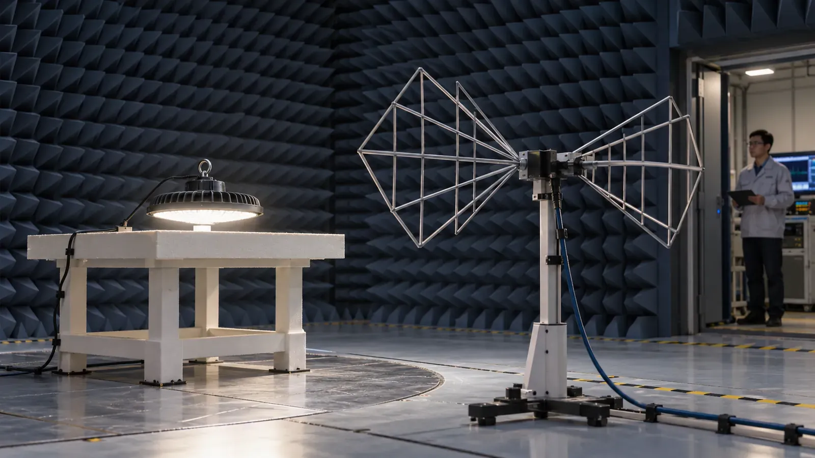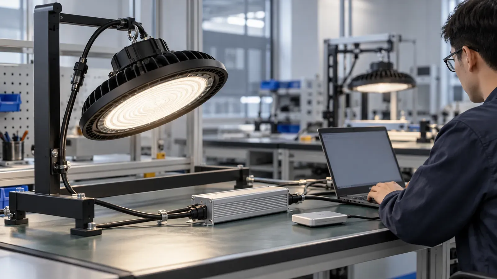
A high-bay quotation marked “150 W with CLO” leaves two important questions: is 150 W the initial input power or the highest scheduled power, and which light output is maintained over time? Those distinctions affect the energy calculation, thermal assessment and the light available when the warehouse opens.
For constant lumen output LED high bay procurement, ask for the programmed profile and complete-luminaire evidence. A driver that supports CLO can still ship with the feature disabled or with settings that do not match the LED assembly. This guide applies when a supplier offers a CLO option; availability must be confirmed for the exact model.
What CLO does in a high bay
Constant lumen output, also called constant light output, usually starts a new LED assembly below its available maximum output and increases drive over operating time to compensate for expected lumen depreciation. Signify’s driver design-in guide documents a programmable time-based CLO curve.
For that type of implementation, the driver follows a model rather than measuring the warehouse’s actual task-plane illuminance. The outcome depends on the depreciation assumptions, remaining drive capacity and operating conditions. It does not guarantee constant lux at every point in a changing installation.
1. Separate four different functions
| Function | Main purpose | Procurement evidence |
|---|---|---|
| Constant-current driver | Regulates current at its selected operating point | Current setting and output operating window |
| CLO profile | Compensates modeled aging over time | Time/current or time/output table and its basis |
| High-end trim | Limits commissioned output | Initial setting and permission to change it |
| Daylight/occupancy control | Responds to daylight or use | Sensor logic, setpoints and control priority |
A constant-current label does not prove CLO support. A DALI interface does not prove the feature is enabled. Conversely, some programmable drivers provide autonomous CLO without a building controller. Verify the offered driver and firmware rather than inferring capability from the interface name. The DALI-2 versus 0–10 V guide helps define the rest of the control system.
2. Request the profile and its physical limits
Ask the manufacturer to declare the target luminaire flux, initial current, scheduled points, final current, compensation horizon and maximum input power. Request the complete LED-load configuration, ambient condition and evidence behind the depreciation model. LED-package projections alone do not establish the behavior of the assembled high bay; use the LM-79, LM-80 and TM-21 guide to distinguish those evidence types.
Clarify how the driver counts time: powered hours, light-producing hours, treatment of dimmed operation, standby and power interruptions. These rules are implementation-specific. Signify’s programming manual provides a practical example of schedules with working-hour and output-level entries; it is not a universal programming procedure for every driver.
The assembly needs reserve output capacity. If the specified flux already requires the maximum permitted current when new, there may be no useful compensation headroom. At the end of the profile, current, voltage and driver output power must remain within the approved LED and driver limits. Ask what happens after the programmed horizon or if thermal protection limits output.
3. Compare energy using the power curve
Record initial, maximum and time-weighted input power separately. Do not calculate lifetime energy from the first-day wattage alone, and do not assume that input watts track LED current perfectly: LED voltage and driver efficiency also matter.
Consider an illustrative single-luminaire comparison over 40,000 operating hours. Suppose a verified input-power profile rises linearly from 120 W to 150 W. Its average is 135 W and energy is 135 × 40,000 ÷ 1,000 = 5,400 kWh. A fixed 150 W alternative over the same hours uses 6,000 kWh. The difference is 600 kWh, or 10% in this example.
These are calculation assumptions, not a product saving claim. For a fair proposal, both alternatives must meet the same maintained lighting requirement and use consistent cleaning and replacement assumptions. A permanently trimmed 120 W alternative is not equivalent if it cannot meet that requirement later. For a stepped or nonlinear profile, calculate energy for each interval; include control schedules, standby and any auxiliary consumption without counting savings twice.
4. Keep dirt and failures in the maintenance calculation
A time-based CLO curve compensates modeled source depreciation. Dust on lenses, dirty room surfaces, failed drivers, shifted optics and new rack obstructions remain separate issues. Do not set the whole maintenance factor to 1.0 merely because CLO appears in the quotation.
Use the warehouse maintenance-factor guide to document the remaining losses and cleaning plan. If the designer adjusts the lumen-maintenance component to reflect CLO, require a clear compensation basis and avoid counting the same aging loss again. The photometric-file guide helps identify whether the design file represents commissioned CLO output or unrestricted new-luminaire output.
5. Verify temperature and interaction with other controls
Validate the complete assembly at the highest relevant scheduled output and worst declared ambient temperature, not only the lower commissioning setting. Ask for the driver’s case-temperature result at its specified measurement point and the corresponding lifetime/failure assumptions. The high-temperature high-bay guide explains the importance of the whole thermal system.
Manufacturer programmable-driver documentation lists CLO alongside dimming functions; their coexistence still needs configuration review. Specify how CLO interacts with high-end trim, daylight dimming, occupancy, thermal protection and emergency operation. Require an agreed priority and recovery behavior after loss of control communication or supply.
If a sensor maintains task-plane illuminance in a closed loop, review how that loop and the aging profile interact. Test for smooth transitions and stable settings rather than stacking independent compensation assumptions. Use the warehouse sensor-zoning guide for commissioning locations and setpoints.
6. Approve programming and plan replacements
Factory acceptance should confirm the programmed profile, enable state, current limit, firmware and hour-counter state against the approved configuration file. Read settings back from sampled drivers and link the result to luminaire serial numbers. At pre-shipment inspection, measure initial input power and flux or agreed photometric quantities under defined conditions.
Use a manufacturer-approved demonstration or test method for later profile points where available. Such a check verifies programming and electrical behavior; it does not recreate years of LED aging or prove maintained output over life. Keep the demonstration state separate from the production setting and verify the delivered configuration afterward.
Replacement needs an explicit procedure. A new driver serving an aged LED board may need a different starting state from an entirely new luminaire. A new LED board paired with an old driver’s accumulated hours may receive an inappropriate setting. Ask the manufacturer how to restore or revise the profile and counter in each case, including access tools, records and limits. Do not reset counters automatically without that assessment.
CLO wording for a high-bay RFQ
For [model and LED/driver configuration], provide the offered CLO function, target flux, initial current, time-based profile, final current, compensation horizon and initial/maximum input power. Identify depreciation evidence, ambient conditions, hour-counting rules and operation after the horizon. Submit thermal verification at the relevant maximum setting, control-priority rules, programming readback and production traceability. Lighting and energy calculations shall use the agreed maintained target, remaining maintenance losses and complete power profile. Provide separate service instructions for driver replacement, LED-board replacement and complete-luminaire replacement.
Include destination-market and other technical requirements through the industrial-lighting RFQ checklist. When asking about a UFO high bay, identify CLO as an option to confirm and request evidence for the specific assembly, not just the driver’s feature list.