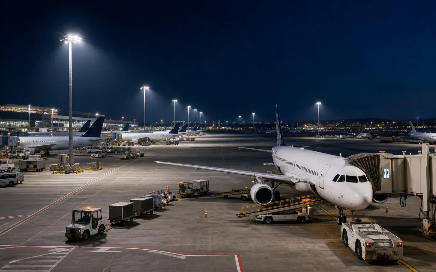
Airport apron lighting must support marshalling, fueling, baggage handling, catering, inspection and vehicle movement without confusing pilots or creating glare for the tower and ground crews. A generic high-mast calculation based only on horizontal lux is incomplete.
B2B priority: provide aircraft stands, service routes, observer positions and pole constraints before the supplier selects optics. Airport operations and photometric design must be coordinated.
Define the apron tasks and stakeholders
Map stand types, aircraft envelopes, passenger bridges, fuel zones, equipment staging, service roads, terminal glazing and control-tower sightlines. Record temporary or future stand arrangements.
Include airport operations, airline/ground handlers, air traffic control and maintenance teams in the review. FAA airport-design guidance recommends stakeholder coordination for apron area lighting and refers designers to applicable IES practice (FAA AC 150/5300-13B).
Calculate more than pavement illuminance
Ground workers need to see aircraft surfaces, chocks, markings, people and equipment. Define horizontal and vertical calculation planes relevant to the tasks. Review minimum values and uniformity as well as averages.
Model shadows from the aircraft, passenger bridge and service vehicles. Overlapping distributions can reduce hard shadows, but excess cross-aiming may raise glare.
Control glare and pilot confusion
FAA guidance advises aiming apron luminaires downward, using baffles or shields to prevent uplight and creating uniform coverage with overlapping sources. Establish critical observer views from cockpit heights, apron vehicles, marshalling positions, terminal windows and the tower.
Do not add shields after procurement without recalculating useful light and wind area. Use the outdoor glare and spill guide for a structured observer-based review even though sports metrics are not automatically airport criteria.
Select optics with traceable files
High-mast apron layouts often combine narrow, medium and asymmetric optics. Require exact model-specific IES or LDT files and an aiming schedule. Validate them using the photometric-file checklist.
For each floodlight record:
| Data | Purpose |
|---|---|
| Pole and bracket ID | Installation traceability |
| Mounting height and coordinates | Calculation control |
| Optic code | Correct distribution |
| Horizontal/vertical aiming | Field alignment |
| Shield/louver code | Glare and uplight control |
| Wattage/control address | Energy and scene setup |
Coordinate pole and airspace constraints
Pole locations and heights must be reviewed against airport obstruction criteria and operational clearances. The FAA notes that apron poles must not exceed applicable obstruction standards and may require an airspace determination.
Provide the structural engineer with luminaire weight, projected area, bracket geometry and aiming range. Include cable loads, access equipment and future additions. Photometric optimization cannot override structural or airspace limits.
Specify the operating environment
Review jet blast, vibration, deicing chemicals, fuel exposure, coastal salinity, temperature, wind and pressure washing. Require suitable fasteners, coatings, cable glands, retention and bracket locking. If the airport is coastal, apply the corrosion controls in the port and container-yard guide.
Hazardous-area classification near fueling operations must be determined by the responsible engineer. General apron floodlights should not be represented as suitable for a classified location without the required approval.
Plan controls and maintenance
Create scenes for active stands, inactive apron zones, security and emergency operation. Define manual override, communication loss and power-restoration behavior. Keep safe movement routes visible.
For a modular LED floodlight, review driver, SPD and optical-module service at installed height. Record spares and aiming marks so a replacement returns to the approved position.
Commission under real conditions
Verify aiming at night with representative aircraft and equipment where possible. Measure agreed horizontal and vertical points, inspect critical observer views, test scenes and record final settings. Photograph brackets and aiming indicators for the asset file.
RFQ clause
“Submit an airport-apron calculation using final stand geometry, aircraft envelopes, service routes and observer locations. Provide model-specific photometric files, aiming schedule, glare/uplight controls, pole-interface loads, environmental evidence, control scenes and maintenance method. Final acceptance includes nighttime aiming and operational stakeholder review.”